
Some Vaguely Scenic Work

Up until now everything I have done has been on the non-scenic part of the layout. The station approach board is the first that has to be scenic, and whilst I don't want to get into the scenery yet, the one job I need to do before laying the track is to colour over the new cork and track bed so that when it is ballasted some years hence it will blend in nicely.

Here is the board with the cork laid on it

/images1014/StationApchBoard2.thumbnail.jpg

And here it is with a bit of colour

/images1014/StationApchBoard4.thumbnail.jpg

I am using the Chris Nevard recommended "misting" with cans of red oxide, matt black, and primer grey. It doesn't need to be a work of art right now because most of it will not be seen, all that is necessary is to remove the shiny newness of the cork and surrounding board.

Control Panel Shelf

Having finally completed the fiddle yard control panel I have built a shelf to mount it and a controller socket fascia on.

The control panel is easily moved elsewhere - requiring only the three cables (one power two signal) to be unplugged and moved elsewhere.

Having mounted the control panel I have found the 9000 mcd leds I have used to be blindingly bright....ah I think I am going to have to open up the panel box again and fit some resistors - easier than changing the LEDs. Still thats for another time.

For the next panels I will use perhasp 300 or 400mcd LEDs.

/images1014/controlpanelshelf2.thumbnail.jpg

PCB Mounting Boards

Working on the next under layout mounting boards for the various electronics PCBs that control the points and occupancy detection (and perhaps signals later)...

Here are the next two (of 5 so far) completed, at least as far as wood and metalwork is concerned...

/images1014/PCBMountings.thumbnail.jpg

Laying Cork and Thinking Track

I have been really busy working on a smartphone video monitoring system called Manything lately so haven't had much time for modelling...

LINK}:-http://www.manything.com; Manything Website;

The odd moment I have had, I have cut and laid the cork for the track work on the station approach board. As this is the first scenic section I have cut the cork at a 60 degree angle in order for the ballast to sit nicely on it.

I made the cutter shown below by cutting a piece of 2x2 at 60deg using the compound mitre saw, and the screwed a box cutter blade to the surface - it seems to work ok.

/images1014/60degreeCorkCutter.thumbnail.jpg

I have also tried using the suggestion from Richard at DCC concepts to modify a peco point to take away the horrible chunks of plastic that make it look very unprototypical.

/images1014/soldered_sleepers.thumbnail.jpg

The modification requires soldering copper clad sleepers to replace the original yeuchy plastic.

/images1014/Placed_Trackwork.thumbnail.jpg /images1014/Pre-Cork.thumbnail.jpg

On to a new board

Hmmm so after several months of work I am still struggling to get all the gremlins out of the over-complex control panel. So I have turned my mind back to woodwork. Everytime you do woodwork you remind yourself that almost all wood you can buy is expensive and warped...

More expensive this time as I had a couple of big sheets of ply for the next couple of boards and so needed to pay a delivery charge from Inverness.

I have used my standard wall mounted L-girder technique - though the pictures below show with only one girder fitted.

I have used 100mm sections to hold baseboard surface rather than previous 90mm as this gives just a little more room for getting edge connectors on and off the Tortoise point motors.

/images1014/SAB_Side.thumbnail.jpg /images1014/SAB_From_Below.thumbnail.jpg /images1014/SAB_End.thumbnail.jpg

Class 128

Despite frequent resolutions to not buy any more stock - I am sucker for some things. I loved the new Heljan 128 Diesel Parcels Unit in green with speed whiskers.

It is a lovely heavy model, unfortunately Heljan have cost reduced their packaging from their lovely strong boxes to the same sort of system used by Bachmann and Hornby - you can see the result here -

/images1014/Class128Bits.thumbnail.jpg

I could have sent it back back; but it appears that I was far from alone in having this problem and would probably have just received a replacement with similar problems. Therefore out with the glue and some careful gluing got most of the pieces back on.

Taking it apart meant removing four small bolts and prising the body off - it would be easy to damage the fittings in the cab ends getting the body on and off.

I used a TCSEU621 decoder which seemed to fit in easily into the 21 pin socket.

/images1014/Class128bodyoff.thumbnail.jpg

Panel Testing

The panel works (mostly) but there are some gremlins to get out, not all of which I think are my making...

The green LEDs show position of points, the blue LEDs show section occupancy.

There are also red and yellow leds to show if computer or human has control of a track - but these are not lit in this test.

/images1014/Panel_Testing.thumbnail.jpg

Control Panel Continued

I am sure there must be a better way to do this...

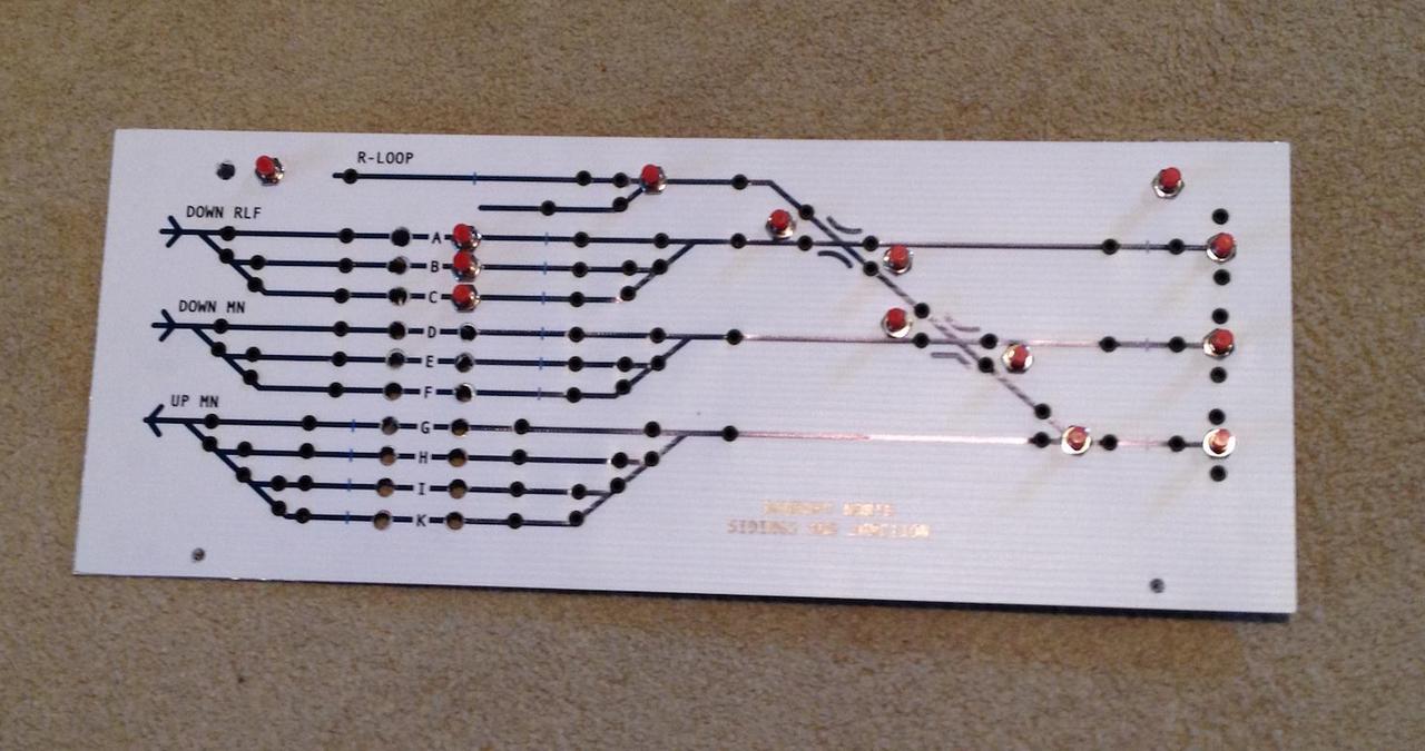
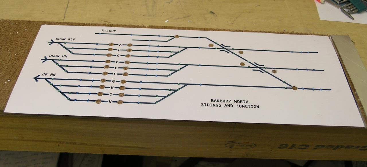
I have ended up drilling more than 120 holes in the aluminium and the paper - and they have to line up!!

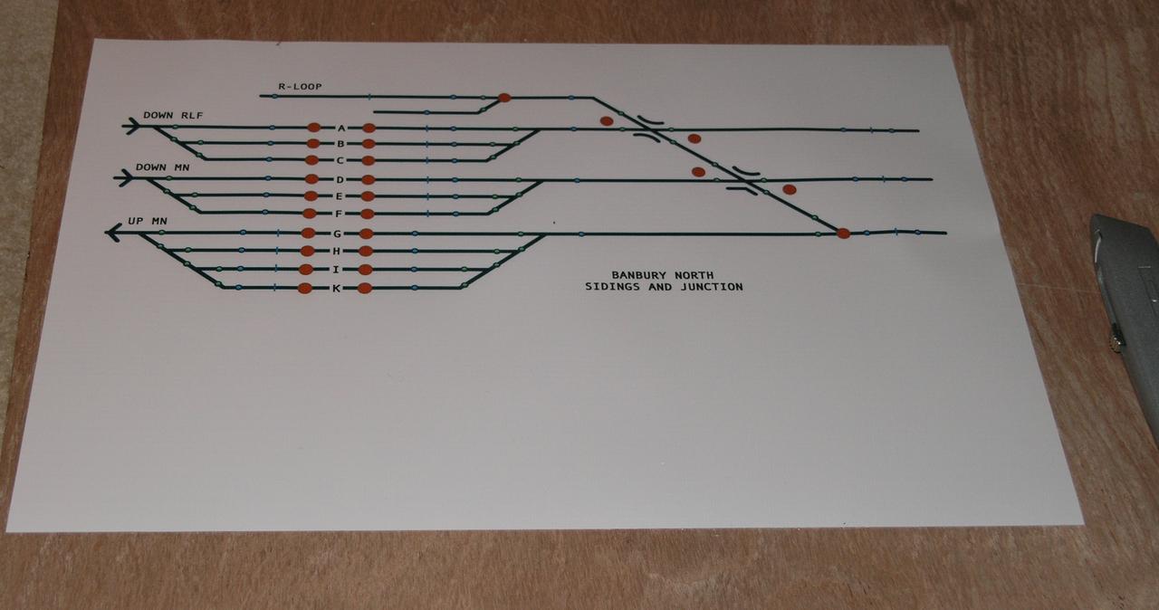
Here is the 1.5mm Aluminium and the paper with their holes in place...

/images1014/Ali_Drilled.thumbnail.jpg /images1014/paperholes.thumbnail.jpg

In the unlikely event that you are a materials scientist looking for a material that will resist all attempts to glue it, then I strongly suggest the combination of waterproof paper and aluminium, they have resisted every attempt to glue them together - including, copydex, superglue, pva (all presumably fail because od the lack of air getting to the glue) - more surprising is that araldite failed as well - as this shouldn't need air having its own chemical fixer.

Anyway I have decided that the large number of switches and leds can be used to hold the paper in place. This does mean that I will need to use LED holders rather than just glue the LEDs into the bare holes - LED holders are a bit fiddly and are hard to get just right in terms of hole diameter - either too sloppy or require an industrial press to get the things in.

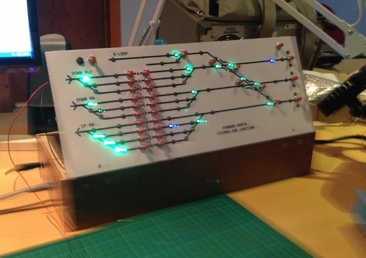
Anyway here is a test fit with some switches...

/images1014/paper_and_ali.thumbnail.jpg

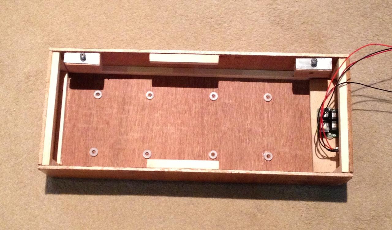
The final piece of the jigsaw is the box, which has two DTM30 boards from CML electronics. To make the connections easier - I have mounted a passive LocoHub4 board that I made up from a blank PCB provided by Huib Maaskant in the Nethernlands. This then connects to each DTM leaving two external facing ports.

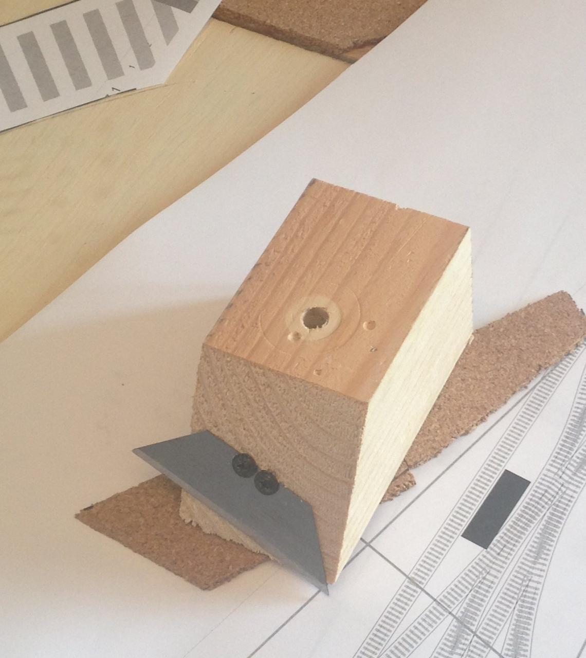
I have made the box out of thin ply, a mistake I think and I am not happy with it for various reasons. I have used two M5 rivnuts mounted in aluminium offcuts and glued onto wooden holders to give me something to screw two roundhead M5 bolts into to secure the front panel.

/images1014/box_and_boards.thumbnail.jpg /images1014/box2a.thumbnail.jpg

Control Panel

The layout is going to need three control panels. I have decided to make a start on one (the one for the fiddleyard and junction) before I progress with the next bout of woodwork.

The electronics are the easy part (remind me I said that later) I am going to use two CML DTM30 boards in a single box. The box will have approx 25 point/route setting push to make switches and around 70 LEDs to show occupancy and point / route setting.

My main concern being a messy sort who has little design skill or flair for such things is how to make the panel look acceptable.

I have started by drawing up the panel I want on Excel and the printing that to pdf for an A3 size sheet. Then I have sent the pdf off to a printer to print onto some tough waterproof paper (£2.50 per sheet). Here is a picture of the diagram...

/images1014/PanelDiagram.thumbnail.jpg

I had considered sandwiching that between an aluminium base and a perspex top but I found that the perspex was too tricky to drill without it cracking. I could perhaps do ten successfully but here I will need to do a lot more than that. So I have just gone for waterproof paper on a 1.5mm aluminium base -

Here is how the paper arrives through the post...

/images1014/paperuncut.thumbnail.jpg

And here it is after I have cut it to size and drilled some holes in it. I found that using a wood drill the 7mm holes for the switches came out neatly - but the smaller ones for the 3mm leds tended not to cut so neatly so I will drill those after I have stuck the paper to the aluminium.

/images1014/drilledpaper.thumbnail.jpg

Drilling the switch holes in paper and metal separately means I have to try and be fairly precise I expect this will need some adjustment as even with the pillar drill I can see I am slightly out in places. Anyone got a handy CNC machine?

/images1014/alydrilling.thumbnail.jpg

MicroSwitches

I have a small number of SEEP point motors. I prefer to use tortoise for the majority, but there are some locations where space is at a premium and the much smaller SEEP seemed to be the answer.

Alhough I bought SEEPs with built in polarity switching - I didn't find it reliable, so I bought some microswitches and placed the reed part of the microswitch so it would be moved by the bottom part of the actuating rod that moves the point.

Whilst this sorted the polarity swtiching problems - in practice I just couldn't make the SEEPs reliably reliable - too often they would not throw. On advice from Laurence at CML I upped the voltage of the SEEP feeds - but whilst an improvement still didn't give me the reliability of switching that I want. Therefore all bar one have been binned and fiddly work has been done to put tortoises in their place.

The picture below shows one of the microswitches I used... .. thumbnail:: /images1014/microswitch.jpg