Installing more platform wiring
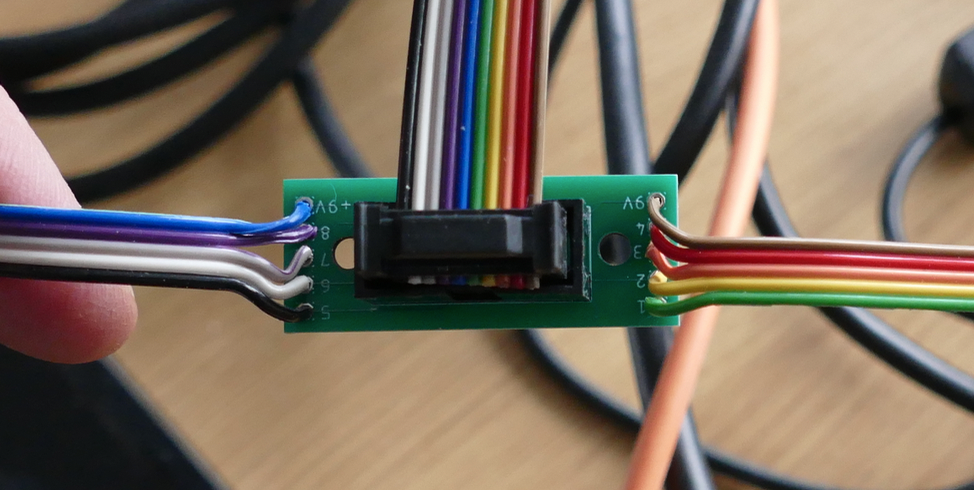
I have been busy fitting the wiring to each of the platforms and testing them. I have built a little test unit comprising a 9V battery and ribbon cable to save me connecting each unit to the PiZero controller to test.
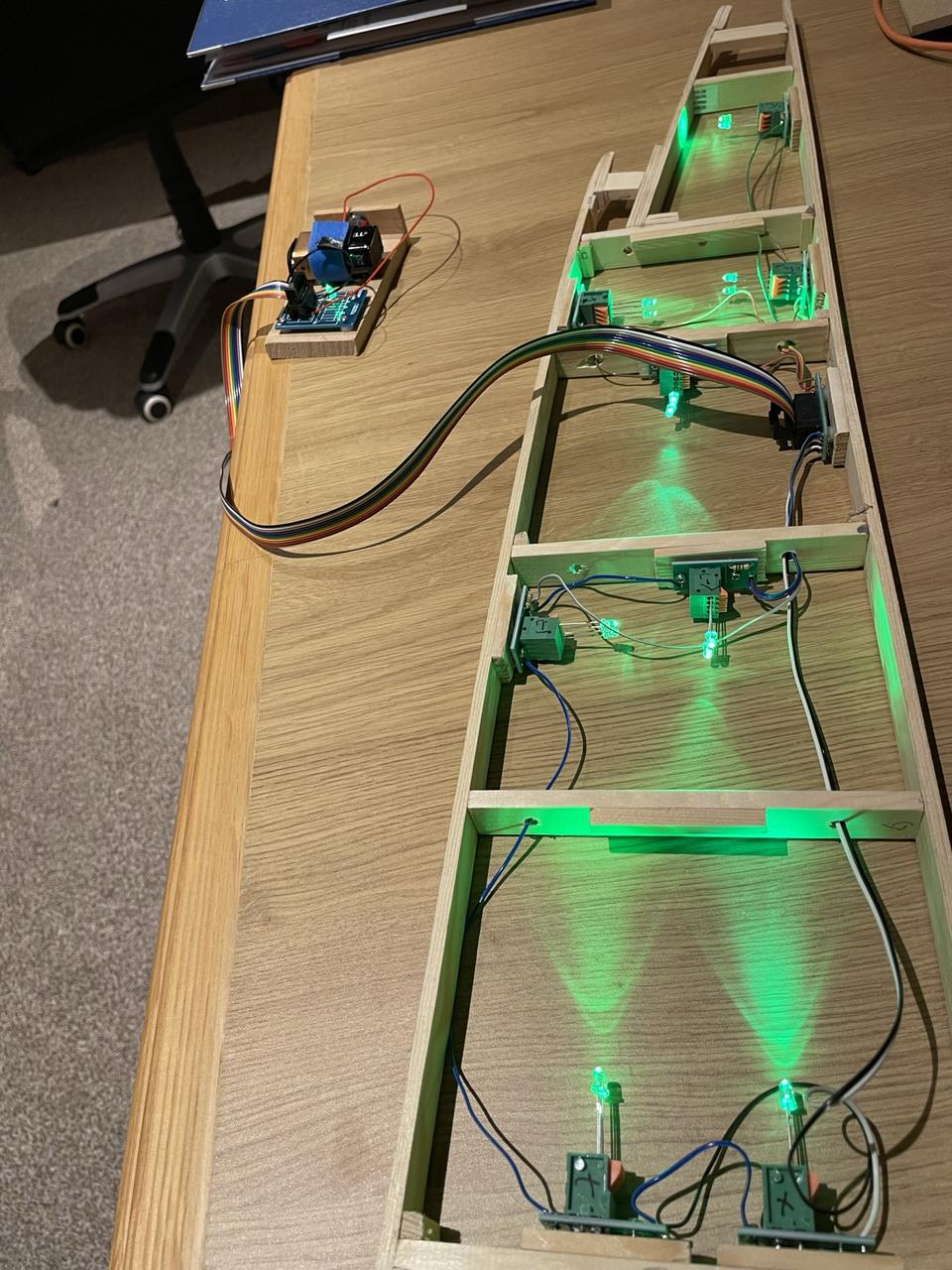
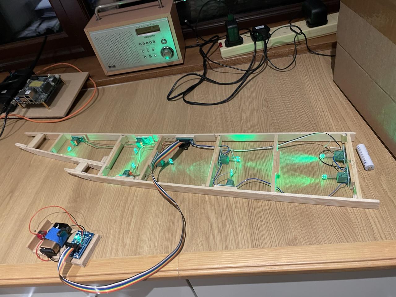
I have been busy fitting the wiring to each of the platforms and testing them. I have built a little test unit comprising a 9V battery and ribbon cable to save me connecting each unit to the PiZero controller to test.
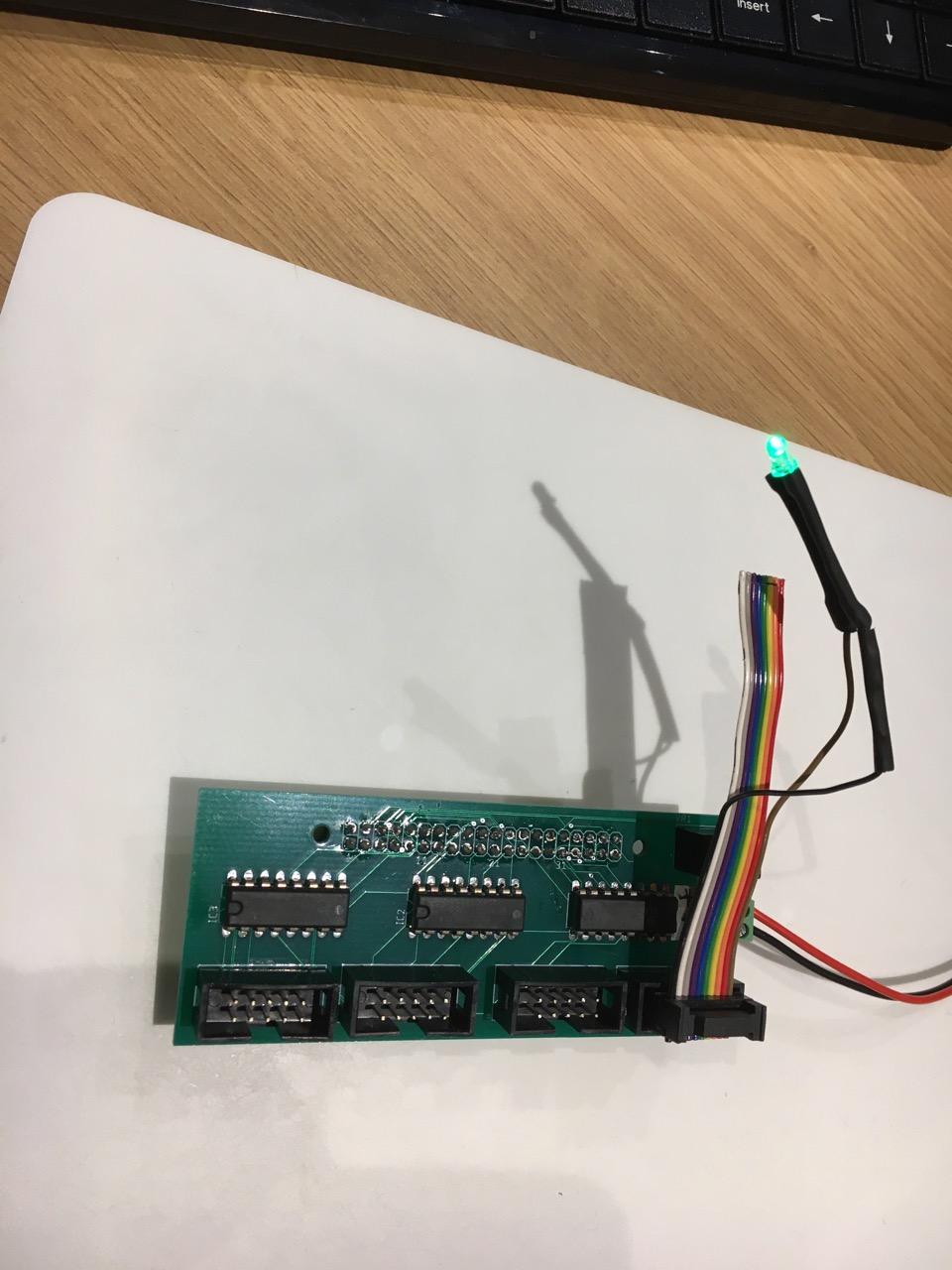
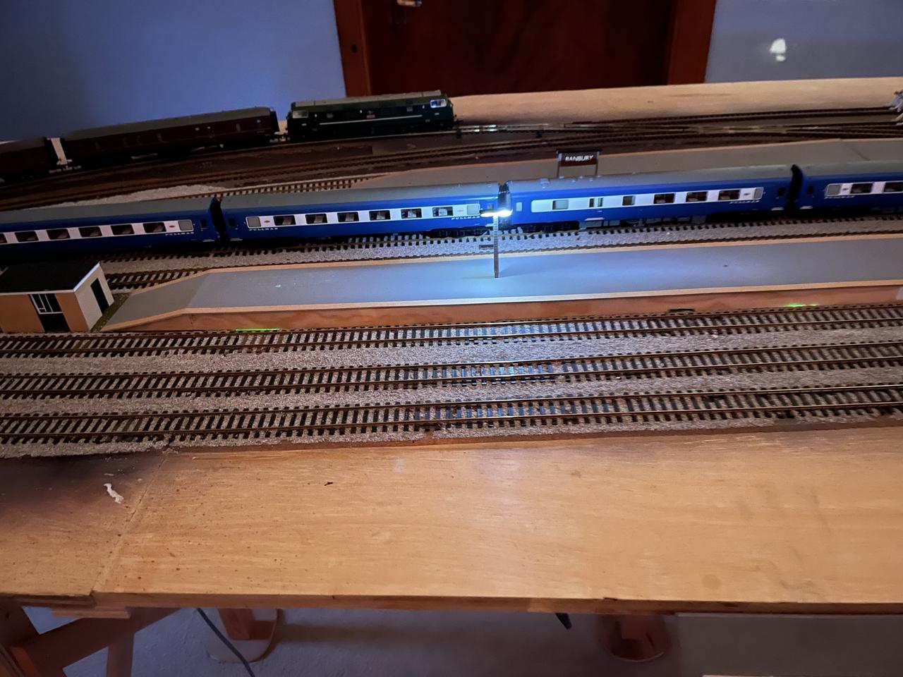
I am now ready to start testing the station lighting system - fistly by just checking the system works at all by using cheap green leds inserted into the screwless spring lever terminal blocks prior to gluing in place the platform top.
Then I have tested with one completed lamppost and one of the station signs I have built.
I am quite pleased with the result.


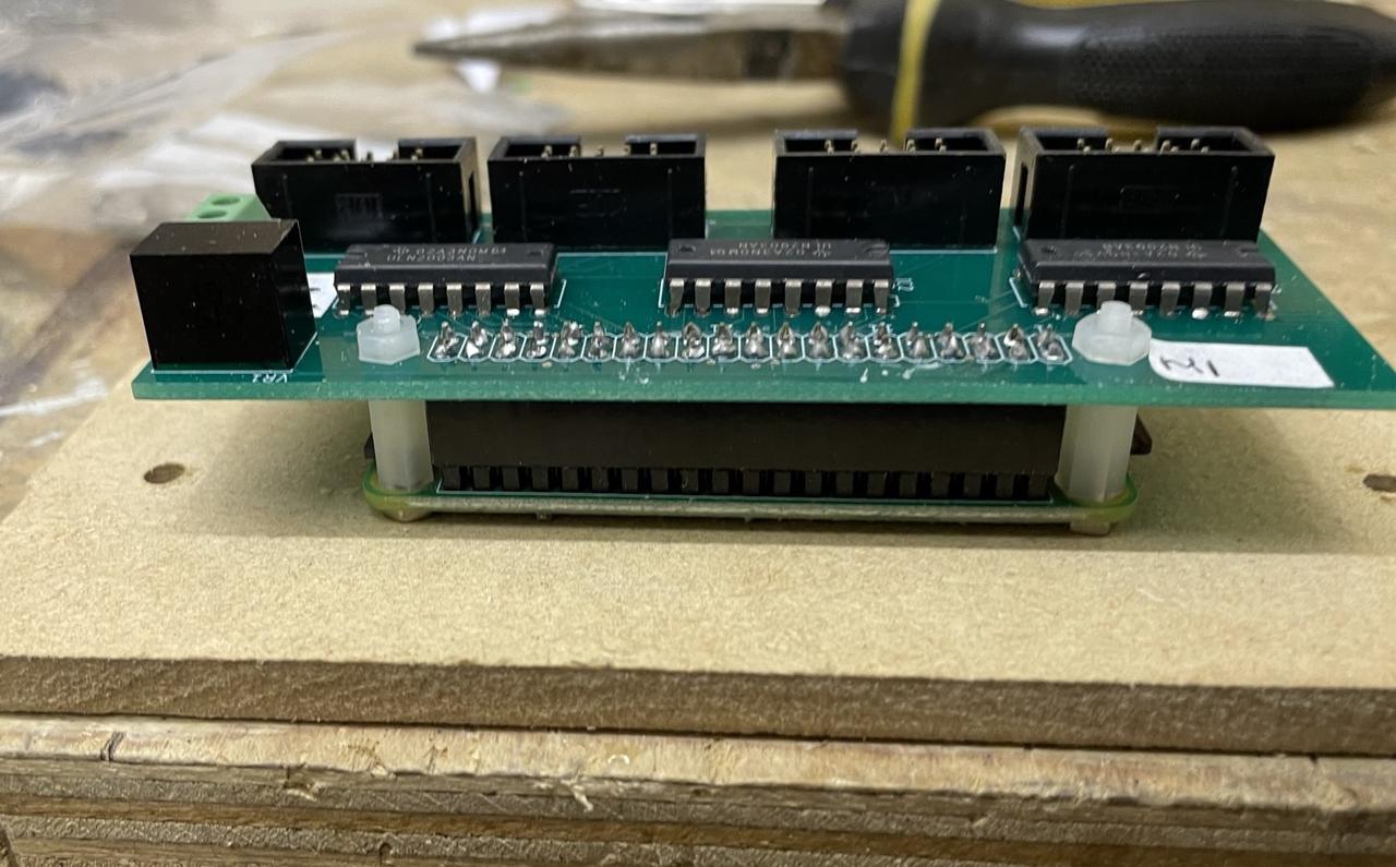
The main lighting controller boards are now ready to be fitted to the Raspbery Pi 2 Zeros and installed under the baseborads.
Each of the four headers will allow 8 pairs of LEDs to operate.
Connecting via 10 way ribbon cable with keyed connectors means as long as you put the connectors on the right way around when you make up the cables you can't get the wrong polarities at the business end.


I have stupidly been working on what has become a large piece of software for automatically controlling the signals in the layout - possible because I know which sections are occupied and can track point state changes. Automatic signalling is not trivial as the code needs to understand the complete connectivity in the layout.
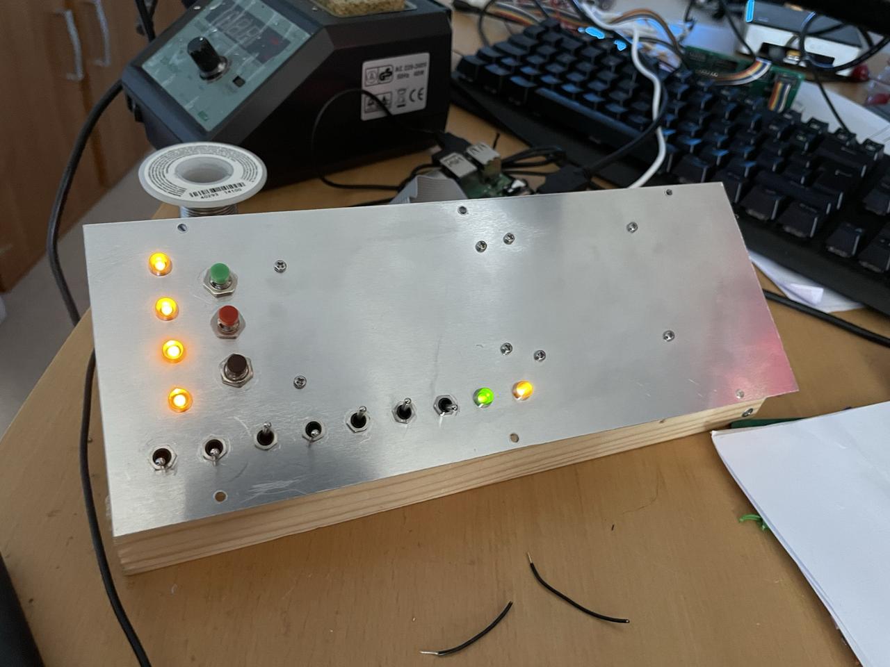
One problem I have is that the dapol semaphore signals seem to 'forget' their polarity from time to time so I have to have an easy method of working around that - so I am building a control panel to have a set of switches which can be used to alter the polarity (and one switch to turn all signals to danger to see if any need altering).
I also want to be able to control the lighting system so have put in some WiFi (UDP) control of the PiZeros that run that - so also have some push buttons for controlling the scenic lighting
I need to get a lot of lighting onto the station building and platforms - each lamppost that I have made requires two miniature LEDs and the building itself will probably need several score. I'd also like for each scenic component to be removable e.g. the platforms. Without a mess of wiring.
Ideally I'd also like the LEDs to be programmable so I can e.g. simulate flickering fluorescent tubes and coz I am a geek.
I settled on using Raspberry Pi 2 ZeroW as the controller device - cheap and with programmable outputs. But each output is very low current maximum and would only drive a couple of LEDs.
So I need some driver circuitry that can be controlled from the Pis - I have chosen a ULN2003A Integrated circuit where each Darlington pair can give 0.5A which is enough to power more leds that you will ever need on one output.
Then I would like to power the Pi from the same power supply as the LED power supply so I will use a little step down DC-DC converter that takes 9V and gives 5V (TSR 1-2450). I want to use 9v so each lamppost pair of lamps can be controlled on a single circuit.
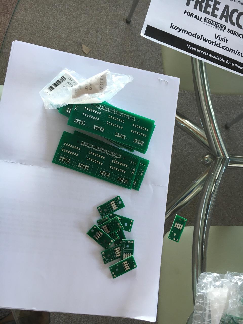
So I have designed three relatively simple PCBs
A Controller 'hat' for the PiZero with four 10 way ribbon cable connectors and one 2 way PCB terminal block for power input.
A 10 way break out PCB particularly for use under the platforms so can have a maximum width of around 16mm.
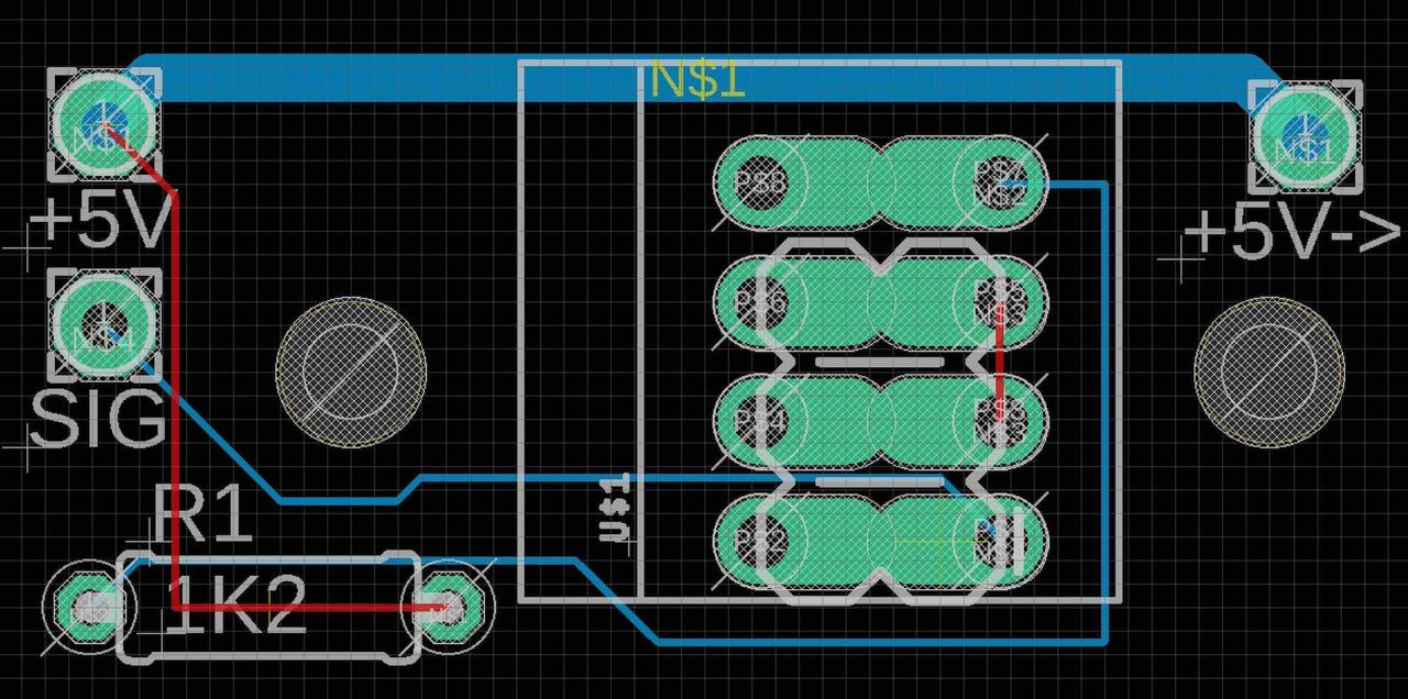
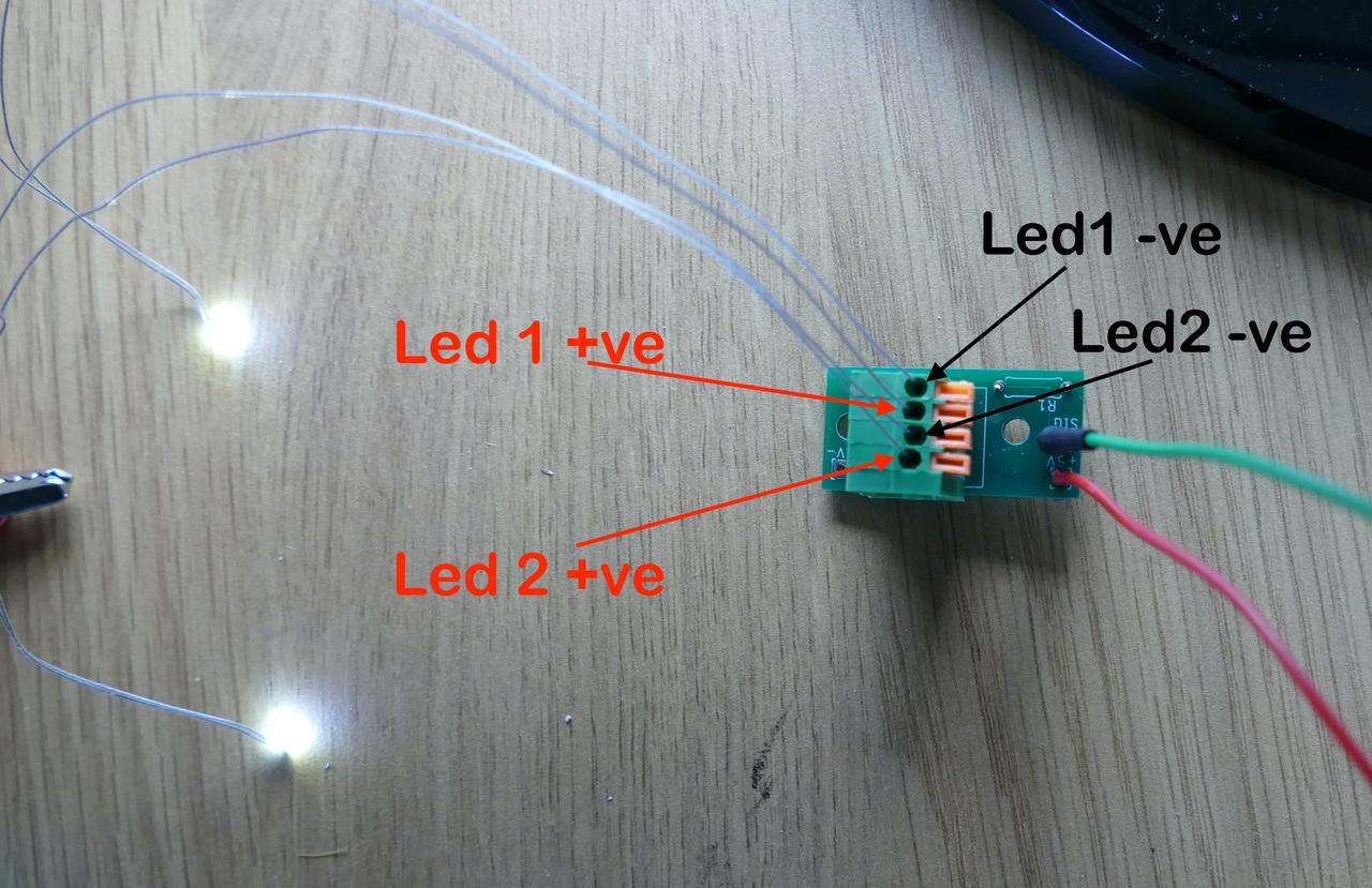
A terminal block and resistor PCB that will connect two LEDs via lever connectors and have a location for the resistor
I have designed these in Eagle (before I switched to the much preferable open source KiCad as Eagle has been destroyed by Autocad).
It is incredibly cheap to have PCBs made these days each one is under a pound for production and shipping.
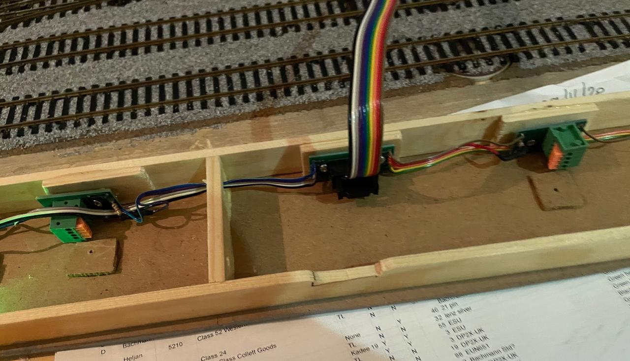
So I mount the PiZero with the hat under the circuit with a single 9v feed then a 10 way ribbon cable runs to the underside of the platform that then feeds the individual terminal blocks which can connect one or two LEDs each on their own circuit.
My intention then is to have wireless control of the LEDs from a single master Pi or similar.